Revitで複動シリンダの空気圧回路図を作図してみた
2026-08-16
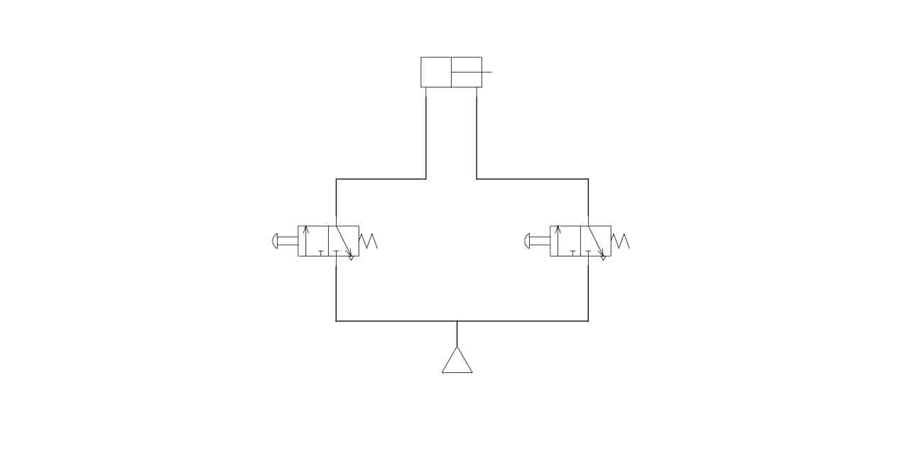
今回は、Revitで複動シリンダ1本を使った簡単な空気圧操作回路を作図しました。
作図に必要な空気圧源、複動シリンダ、3ポート2位置手動弁のシンボルも、一般注釈テンプレートからファミリとして作成しましたので記録します。
製図ビュー
作成したファミリを製図ビューに配置してみました。
シンボルファミリを読み込んで配置する操作は、2D CADに近い感覚で使用できました。
今後シンボルファミリを増やしていけば、空気圧回路図だけでなく、油圧回路図やP&IDの作成にも展開できそうです。
課題
今回は一般注釈テンプレートからファミリを作成しましたが、シリンダの配管接続部に線をスナップできませんでした。
今後、より適したファミリテンプレートや作図方法を検討する予定です。
識別情報のパラメータ
ファミリには、識別情報のパラメータを仮設定しています。
今後、これらの属性をタグ表示や集計に利用したいと考えています。
単なる2Dシンボルではなく、属性情報を持つ図面記号として扱えるようにすることが目標です。
ダウンロード
作成したファミリと確認用プロジェクトは、ページ下部のNavigationからダウンロードできます。
English
Testing a Pneumatic Circuit Diagram in Revit
August 16, 2026
This time, I created a simple pneumatic control circuit in Revit using one double-acting cylinder.
I also created symbol families for the compressed air source, double-acting cylinder, and 3/2 manual valve using the Generic Annotation template.
Drafting View
I placed the families in a Drafting View.
Loading and placing the symbol families felt similar to working in 2D CAD.
By expanding the symbol library, I think this method can also be used for hydraulic schematics and, in the future, P&IDs.
Issue
The families were created using the Generic Annotation template, but I could not snap the piping lines to the cylinder connection points.
I plan to test another family template or drawing method.
Identity Data Parameters
I added some basic Identity Data parameters to the families.
In the future, these parameters may be used for tags and schedules.
My goal is to use the symbols not only as 2D graphics, but also as drawing objects that contain useful information.
Download
The families and the sample Revit project can be downloaded from the Navigation section below.